
Applications - Technology insights
Connection to Pixhawk autopilots Teraranger Evo
TeraRanger Evo
Connection to Pixhawk Autopilots
Connection to Pixhawk Autopilots


Table of contents:
1 Introduction
2 Compatibility table
3 Wiring Connection to Pixhawk
3.1 TeraRanger Evo wiring connection – Pixhawk 2.1
3.2 TeraRanger Evo wiring connection – Pixhawk 1
4 Setup the onboard firmware steps to follow:
4.1 PX4 – QGroundControl
4.2 ArduCopter – QGroundControl
4.3 ArduCopter – APM Planner 2
4.4 ArduCopter – Mission Planner
1 Introduction
The purpose of this document is to explain how to connect a TeraRanger Evo sensor to a Pixhawk board through the I2C interface and how to setup PX4 or ArduPilot firmware to enable TeraRanger Evo sensor use.
2 Compatibility table
At the time of writing, to make the TeraRanger Evo sensor work you must use the developer build version of Arducopter or a PX4 version higher than v.1.7.0. QGroundControl makes it easy to flash the required firmware through the advanced settings. For APM 2 software, see here: http://firmware.ardupilot.org/. Refer to the table below for compatibility.


3 Wiring Connection to Pixhawk
3.1 TERARANGER EVO WIRING CONNECTION - PIXHAWK 2.1
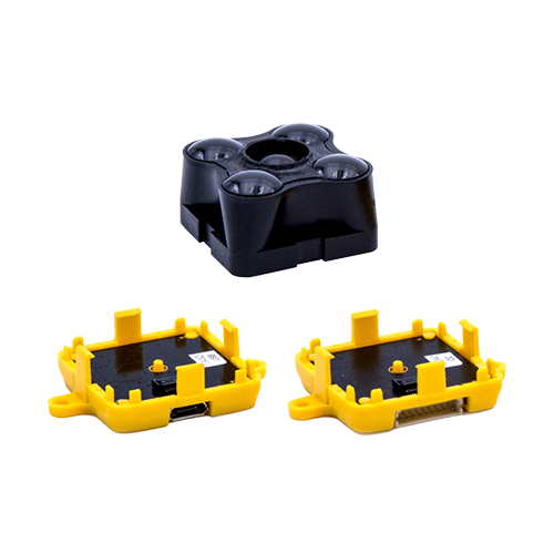
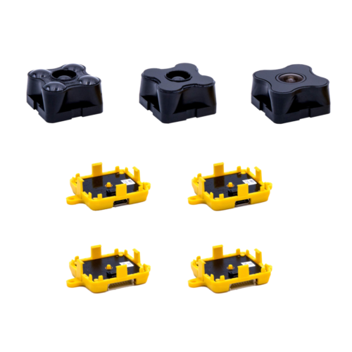
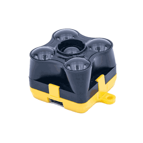
For brevity we will refer to TeraRanger Evo as TR-Evo. To connect a TeraRanger Evo sensor module to Pixhawk please make sure you have a TeraRanger Evo I2C version, composed of:
TR-Evo sensor
TR-I2C/UART backboard
DF13 9P to open-ended cable
For brevity we will refer to TeraRanger Evo as TR-Evo. To connect a TeraRanger Evo sensor module to Pixhawk please make sure you have a TeraRanger Evo I2C version, composed of:
TR-Evo sensor
TR-I2C/UART backboard
DF13 9P to open-ended cable

To connect the sensor to the Pixhawk, please use the open-ended cable and make your connection as shown below:
Pixhawk I2C connector ref is : JST-GH 4pins
Pixhawk I2C connector ref is : JST-GH 4pins

To connect the sensor to the Pixhawk, please use the open-ended cable and make your connection as shown below:

Then connect the cable to the Pixhawk I2C port:
3.2 TeraRanger Evo wiring connection – Pixhawk 1
For brevity we will refer to TeraRanger Evo as TR-Evo. To connect a TeraRanger Evo sensor module to Pixhawk please make sure you have a TeraRanger Evo I2C version, composed of:
1. TR-Evo sensor
2. TR-I2C/UART backboard
3. DF13 9P to open-ended cable
1. TR-Evo sensor
2. TR-I2C/UART backboard
3. DF13 9P to open-ended cable
To connect the sensor to the Pixhawk, please use the open-ended cable and make your connection as shown below:

Pixhawk I2C connector ref is : DF13 4pins

Then connect the cable to the Pixhawk I2C port:

4 Setup the onboard firmware steps to follow:
4.1 PX4 – QGROUNDCONTROL
Note: Please always use the latest QGroundControl version, available from:
Note: Please always use the latest QGroundControl version, available from:
1. Launch QGroundControl software
2. Open Vehicle setup menu and go into the Firmware tab (unplug and replug autopilot if needed).
Select the latest stable release of PX4 Flight Stack. Press the Ok button to flash the autopilot.Go to: Parameters/Sensor Enable
2. Open Vehicle setup menu and go into the Firmware tab (unplug and replug autopilot if needed).
Select the latest stable release of PX4 Flight Stack. Press the Ok button to flash the autopilot.Go to: Parameters/Sensor Enable

3. In the field SENS_EN_TRANGER select your TeraRanger sensor type:
TREvo
Press Save to confirm.
TREvo
Press Save to confirm.

4. After making sure the sensor is connected to the Pixhawk I2C port, reboot the autopilot.
5. To verify that the sensor is operational open an Analyze Widget (Widgets/Analyze). From the list on the left hand side select; M1:DISTANCE_SENSOR.current_distance. The plot showing distance measurements should indicate that the sensor is working correctly.
5. To verify that the sensor is operational open an Analyze Widget (Widgets/Analyze). From the list on the left hand side select; M1:DISTANCE_SENSOR.current_distance. The plot showing distance measurements should indicate that the sensor is working correctly.

4.2 ARDUCOPTER – QGROUNDCONTROL
1. Go to the Firmware tab on QGroundControl (reconnect autopilot in order to flash a new firmware). Select ArduPilot Flight Stack. In the dropdown menu select MultiRotor – APM:Copter.
2. Go to Parameters/RNGFND and update the following fields:
RNGFND_TYPE : 14 / TrOneI2c / TeraRangerI2C
(each of these values should work, but they might appear differently based on the GCS software version.)

3. To verify that the sensor is operational open an Analyze Widget (Widgets/Analyze). From the list on the left hand side select; M1:DISTANCE_SENSOR.current_distance. The plot showing distance measurements should indicate that the sensor is working correctly.

4.3 ARDUCOPTER - APM PLANNER 2
Please make sure you are running the latest version of APM Planner 2, available here:
Please make sure you are running the latest version of APM Planner 2, available here:
1. Open APM Planner. Go to Initial Setup, Instal Firmware and flash the latest firmware of ArduPilot.
2. Click on USB device name on the right hand side and select the appropriate Serial Port and Baud Rate for your device and pressthe Connect button.
3. Go to Parameters/RNGFND and update the following fields:
RNGFND_TYPE : 14 / TrOneI2c / TeraRangerI2C (each of these values should work, but they might appear differently based on GCS software version.) 4. Reboot the autopilot and select the GRAPHS tab. On the right hand side you should see the messages from the autopilot. From the list select; DISTANCE_SENSOR/current_distance:


4.4 ARDUCOPTER – MISSION PLANNER
Please ensure you are running the latest version of Mission Planner, available here:
Please ensure you are running the latest version of Mission Planner, available here:
1. Open Mission Planner. Go to Initial Setup, Instal Firmware and flash the latest firmware.
2. Click on USB device name on the right-hand side and select appropriate Serial Port and Baud 3. 3. Rate for your device and press the Connect button.
3. Go to Parameters/RNGFND and update the following fields:
RNGFND_TYPE : 14 / TrOneI2c / TeraRangerI2C (each of these values should work, but they might appear differently based on GCS software version.

4. Reboot the autopilot and select the Flight Data tab. On the left window you should see a quick tab with displayed value. Double click on one and check SonarRange. The distance is now displayed on the Quick flight data menu.